Table of Contents
flrig as xcvr controller
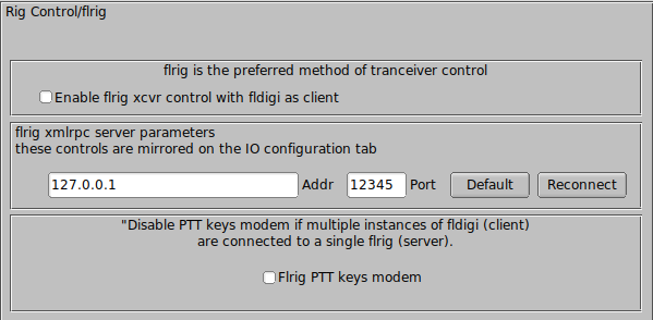
flrig is a separate program that provides nearly 100% control over more than 60 different transceivers. Using flrig with fldigi can enhance your digital mode operating experience. It is the recommended method of control when your transceiver supports CAT operations and has been coded for flrig.
fldigi and flrig communicate changes in transceiver state using the xmlrpc protocol over a local socket. Transceiver control changes may be made at the transceiver, flrig, or fldigi and the change will be annunciated at the other two. These changes are communicated ten times each second. The update limit is usually imposed by the transceiver and the baud rate selected for the transceiver-computer interface. Older transceivers will impose the greatest restriction especially when it's firmware is busy with internal processes.
Select the "Enable flrig xcvr control with fldigi as client" for this method of control. fldigi will attempt to connect to the flrig server and will do so periodically until the connection is established. flrig may reside on the same computer or on another that can be reached on the local area network. The computer address and port must match the location and configuration of flrig. The defaults are local host, 127.0.0.1, and port 12345.
RigCAT xcvr control
RigCAT is a rig control that was developed specifically for fldigi.
It uses command / response definitions that are found in various rig.xml files. You can use a rig.xml file specific for your transceiver or write and test one yourself. The easiest way is to adapt an existing rig xml file for a rig that is similar to your own. ICOM uses almost identical command/response strings for all of its transceiver line. Yaesu rigs have nearly all used unique command/response structures until just recently. The FT-450, FT-950 and others share a similar set of commands and responses.
RigCAT commands and responses are defined in a rig specific xml file which contains all of the required queries and responses in extended markup language format. Please read the specification document rigxml to learn more about this new way of building generic rig interface definitions and how they are used with fldigi. fldigi will look for a file in the $HOME/.fldigi/rigs directory for all files with extension ".xml". These contain definitions for the transceiver indicated by the file name, ie: FT-450.xml, IC-756PRO.xml, etc. You can download the appropriate xml files from the xml archives. Place the file in your rigs directory and fldigi will find it.
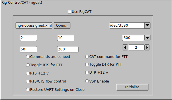
You will need to specify how your PTT will be triggered. This can be using a CAT command, the RTS or DTR pins or none. None would be appropriate if you are using the rig's VOX or an outboard sound card interface such as the SignalLink SL-1+ which produces its own VOX type of PTT. In that case simply leave all of the PTT options unselected.
If you are using a transceiver or a rig interface such as CI-V that echos all serial data you check off the "Commands are echoed" box. That will suppress fldigi trying to respond to a command it just sent to the transceiver.
You may need to try various values of retries, retry interval, and command interval to achieve consistent rigcat control.
Press the Initialize button after setting all of the parameters. If the settings are all correct fldigi should start receiving frequency information from the rig and annunciating them on the rig control frequency display.
Hamlib xcvr control
Hamlib is a set of standard libraries for interfacing to a large number of transceivers. The hamlib library system consists of a front end which acts on behalf of all rigs and backends which are specific to each rig. The hamlib library is not developed or maintained by the fldigi developers.
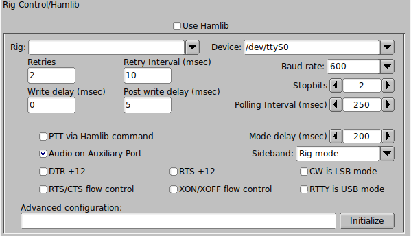
Select your transceiver from the list of supported units. Then select the serial port and baud rate. If you are familiar with the hamlib library you can send various startup sequences to the rig using the advanced configuration. PTT control can be achieved using CAT commands or via DTR / RTS on the same port as the control comms. You might also need to specifiy whether RTS/CTS flow control is uses (Kenwood rigs use this quite often) or if Xon/Xoff flow control is used.
You may need to try various values of retries, retry interval, and command interval to achieve consistent hamlib control.
Press the Initialize button after setting all of the parameters. If the settings are all correct fldigi should start receiving frequency information from the rig and annunciating them on the rig control frequency display.
External program XmlRpc control
Xml-Rpc allows third party software to control various aspects of fldigi operation including but not limited to rig control. fldigi's xmlrpc server is always executing. External programs can concurrently provide rig control using the fldigi recognized xmlrpc commands. This control can be concurrent with other control methods, i.e flrig, fldigi and an xmlrpc client can simultaneously control the transceiver. Only one can be used to send and receive transceiver commands via it's serial i/o stream.
Use hardware PTT only
Serial Port using DTR or RTS
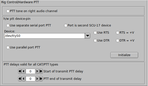
The simplest rig control is just being able to control the push to talk via an external transistor switch. You set this type of control on the hardware configuration tab for rig control.
You select this operation by checking the "Use serial port PTT". Select the serial port from the list (fldigi will have searched for available ports). Enable the "Port is second SCU-17 device" control if you are using an SCU-17 or a similar device which has a dual USB virtual serial port. The SCU-17 Windows driver requires the stop bits to be set to ZERO or the driver fails to correctly initialize.
Then specify whether the h/w uses RTS or DTR and whether a + or - voltage is required to toggle PTT on. The program allows you to use RTS, DTR or BOTH for the PTT signal. Press the Initialize button to restart the serial port with the selected settings.
Parallel Port (Linux and Free BSD only)
Fldigi sets and clears the parallel port pin, PARPORT_CONTROL_INIT, pin 16 on the 25 pin parallel port connector. Keydown sets Pin 16 to +5 volts and keyup sets the voltage to zero.
μH Router (MacOS X)
Simular functionality can be achieved on the Macintosh operating system using 'μH Router' by Kok Chen, W7AY. See μH Router Website for specific details and requirements. A selectable (check box) option will be available on the Rig->Hardware PTT Configuration panel.
PTT delays
You can accommodate delays in transceiver switching between receive and transmit by adjusting the PTT delays. The control values are in milliseconds. These controls have no effect on external PTT circuits such as those implemented in the SignaLink interfaces. They rely on detecting the audio data stream. You can use a combination of macro tags in a macro key definition to achieve a resolution. For example try a macro definition similar to this to insure that the RSID is sent via a slow FM xcvr (or via a VHF repeater)
<TX><MODEM:NULL><IDLE:2.5>
<!MODEM:MT63-500>
<TXRSID:on>
Change the idle time value (in fractional seconds) to suit your needs.
PTT using audio tone
Fldigi can generate a 1000 Hz tone for the duration of the PTT keydown period. When selected this tone is on the right channel of the stereo connector. A simple tone detector/filter and transistor switch can be used to generate a PTT signal from this sound card output. Jim, W5ZIT, has provided details on building a right channel PTT interface for this type of hardware control.
Use Pi GPIO PTT
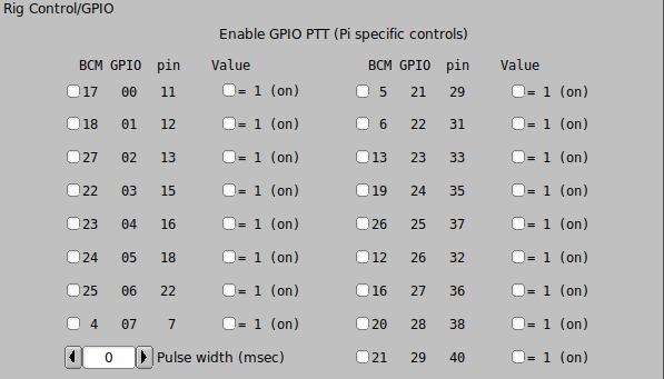
The Pi series of miniature computers offer a large array of possibilities for controlling devices. It has a array of General Purpose Input Output, gpio, lines of a 40 pin in-line header. 17 of these gpio lines can be used for things like push-to-talk. There are several add on boards for the Pi3 and Pi4, such as the NW Digital Radio UDRC-II, that has a full interface for digital operations, including PTT and audio codecs.
Access to hardware ports is always limited to the user who either is root or has root privileges. setuid and setgid (short for set user ID upon execution, and set group ID upon execution, respectively) are Linux access rights flags that allow users to run an executable with the permissions of the executable's owner or group respectively and to change behaviour in directories. They are often used to allow users on a computer system to run programs with temporarily elevated privileges in order to perform a specific task. While the assumed user id or group id privileges provided are not always elevated, at a minimum they are specific.
It is possible to give full gpio access and control privileges by elevating fldigi with setuid root. But this is not advisable as fldigi is also granted access to both serial and network services. There is a way to provide the access via a second program that does have the elevated privilege
This is a copy of material at
https://projects.drogon.net/raspberry-pi/wiringpi/download-and-install/
for installing WiringPi which includes a really nice utility called gpio.
To obtain WiringPi using GIT:
$ git clone git://git.drogon.net/wiringPi
If you have already used the clone operation for the first time, then
$ cd wiringPi
$ git pull origin
Will fetch an updated version then you can re-run the build script below.
To build/install there is a simplified script:
$ cd wiringPi
$ ./build
The build script will compile and install it all for you. It does use the sudo command at one point, so you may wish to inspect the script before running it.
Test wiringPi's installation
run the gpio command to check the installation:
$ gpio -v
$ gpio readall
That should give you some confidence that it’s working OK.
WiringPi is released under the GNU Lesser Public License version 3.
fldigi uses the gpio program for initializing the gpio port, which also happens to the change the privilege of the temporary sys file for setting the port state.
Read the man document for gpio
GPIO is  a  swiss  army knife of a command line tool to allow the user
easy access to the GPIO pins on the Raspberry Pi and the SPI A/D and D/A
converters on  the  Gertboard.  It's designed for simple testing and
diagnostic purposes, but can be used in shell scripts for general if
somewhat slow control of the GPIO pins.

It can also control the IO's on the PiFace IO board and load the SPI and
I2C  kernel  modules if required.

Additionally, it can be used to set the exports in the /sys/class/gpio
system directory to allow subsequent programs to use the /sys/class/gpio
interface without needing to  be run as root."

After installing gpio on your Pi you can set the gpio port on fldigi's
GPIO configuration tab.  The UDRC-II for example uses pin 16, BCM # 23,
for push to talk.  It has an LED indicator on the board to show when PTT
has been enabled.  For this board you select "BCM 23" and select the
corresponding "= 1 (on)" check box.
During start up fldigi uses the gpio program to set up the gpio pins with the command
$ gpio export NN out
This is the command to export a GPIO pin in the /sys/class/gpio directory. Note that the pin number is the BCM_GPIO number. 'out' sets the pin to be an output control, and 'in' an input control.
Once a GPIO pin has been exported, the gpio program changes the ownership of the
/sys/class/gpiogpioX/value
and if present in later kernels, the
/sys/class/gpio/gpioX/edge
pseudo files to that of the user running the gpio program. This means that you can have a small script of gpio exports to setup the gpio pins as your program requires without the need to run anything as root, or with the sudo command.
During shutdown fldigi uses the gpio program to disable access to the gpio pins used with PTT by invoking the command
gpio unexport NN.
You can check that this is working correctly from a terminal window using the command
$ gpio readall
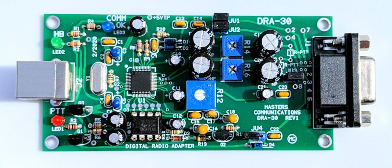
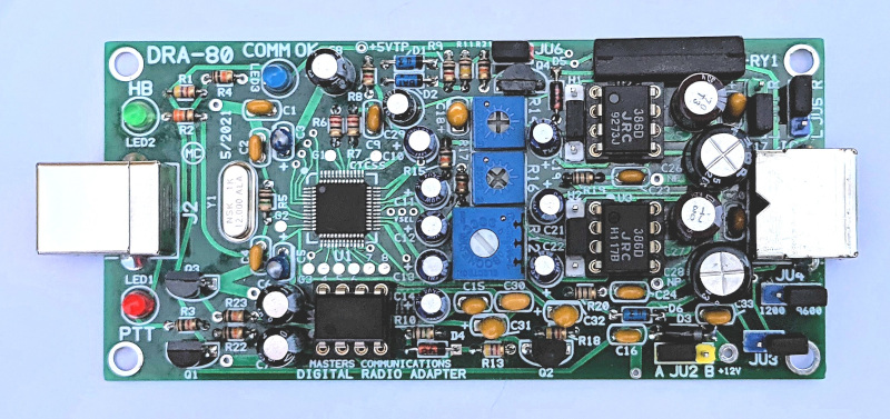
C-Media GPIO PTT
Sound card interface units such as the Masters Communications DRA series use C-Media audio codec chips.
These devices will be enumerated on the sound card devices configuration panel. The C-Media device must be selected for both input and output audio or the GPIO PTT output will not be enabled.
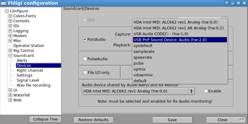
The C-Media GPIO PTT is enabled on a separate rig control configuration panel:
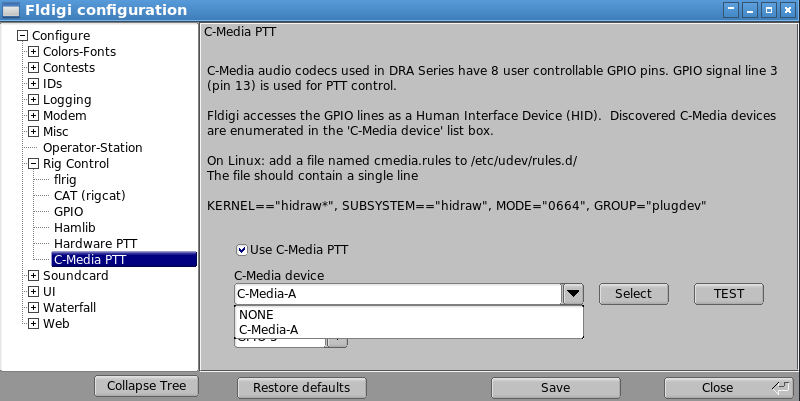
If multiple C-Media devices are discovered they will enumerate as C-Media-A, C-Media-B, etc. You must test the selected interface as it is not possible to know which is the correct one for the DRA interface. Pressing the TEST button will cause the PTT line to rapidly toggle for a period of 2 seconds. This will cause the RED PTT led to flash and the transceiver PTT to toggle on and off.